Dosing, transport and injection of waste wood into a boiler with fluidised bed firing system (hogged wood, residual wood, bark)
1. Introduction
Wood residues and wastes from the manufacturing plants of the wood processing industry are a relatively economical fuel and very suitable for combustion/co-combustion in fossil fuel power stations. A central, regionally favourable site of the power station close to several providers, the low haulage costs associated with this and the utilization of the raw material wood residues by combustion/co-combustion represent both for the producer and for the utiliser an economically and ecologically excellent solution of the waste problem.
In addition to other energy producers, the electricity works Wesertal GmbH in Hameln-Afferde, Germany also operate on their premises an atmospheric bubbling fluidised- bed boiler with a thermal capacity of 124 MW or 140 t/h steaming capacity. For some years now, wood residues from the wood processing industry of the area have been combusted here. Combustion first took place in one or two modules of the 6-module boiler by way of experiment. First of all, preparatory to the co-combustion of the waste wood fuel, the actual boiler had to be modified both for legal licensing reasons and for technical reasons associated with the furnace. Since this method of supplementary combustion proved effective in the experimental stage, the plant has meanwhile been extended and enlarged for the supply to all six boiler modules from a central point. It is now possible to operate the fluidised bed boiler with 100% wood, 100% coal or in a mixed mode. The corresponding dosing, transport and Injection of waste wood into the boiler, including operational experience with the experimental plant for over a year, will be described in more detail in this article.
2. Description of the plant layout and technical data
Since the now reconstructed plant corresponds to the experimental plant in its technical data per line and further over a year of operating experience is available under real conditions with the experimental plant, it is proposed to draw on this experience as well.
During the experimental phase, the complexity and costs of the arrangements for storage and transport of the residual wood were to be kept as low as possible. Therefore, the residual wood was taken directly to combustion from a discharge station using articulated truck trailers with screw extractor units, i.e. it was transported pneumatically to the boiler and then injected at several points directly above the bed surface.
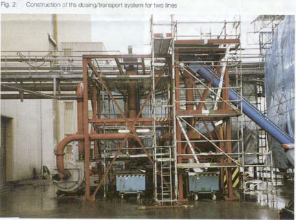
Fig. 1 shows the flow diagram of the plant with its main components (without docking and discharge station) and Figure 2 the construction of the dosing/transport system for two lines. The full dosing capacity at 100% boiler load for pure wood operation is between 24 and 28 t/h. The transport capacity per line was set as 5 (max. 6) t/h.
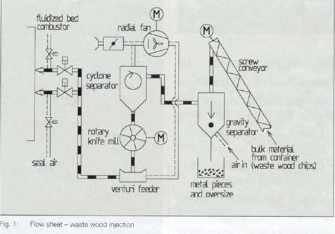
The waste wood is first extracted and proportioned in a screw conveyor. A further rising screw conveyor transports the waste wood to above a vertical downshaft (classifier) down which the material drops vertically under gravity. The air for the radial flow fan is sucked in in counterflow, diverted through 90° in a ring-shaped enlargement and then led in the direction of the fan. In the process the wood and bark pieces become entrained and heavy components (metal pieces, hinges, screws etc.) as well as any oversize are separated. The selectivity of this pre-separation can be influenced by varying the speed of the upward air flow.
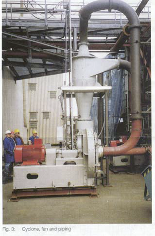
The coarse material falls into an open container which must from time to time be emptied. The cyclone (Fig. 3) installed downstream of the classifier in the direction of flow has produced a decisive improvement in performance.
All the material bypasses the fan, i.e. only air is sucked through it. The residual wood by contrast is separated in the cyclone and admitted over a special knife edge lock as well as a redesigned and optimized feed shoe into the stream of air again.
In the boilerhouse, just in front of the boiler wall, there is a two-way split in the transport line which branches the flow of material into 2 blower lines and/or nozzles. Immediately before entry into the boiler one seal air line is fitted per injection point. This is designed to prevent the apertures in the boiler wall from being blocked when wood transport is interrupted. The transport lines consist of thick-walled mild steel pipe.
The most important technical data of the plant are:
Transport capacity (per blower line): |
5 t/h (max. 6 t/h) |
Transport line length: |
approx. 70 m |
Number of bends: |
5 x 90° |
Transport line diameter before / behind distribution: |
250/200 mm |
Fan output (max.): |
approx. 75 kW |
Installed motor power: |
90 kW |
Fan speed: |
3000 rpm |
Head (max.): |
approx. 160 mbar |
Capture efficiency of cyclone: |
>99 % |
Axial velocity in cyclone: |
approx. 2.8 m/s |
Pressure drop in cyclone: |
approx. 8 mbar |
Motor power knife edge lock: |
3 kW |
Rotor volume: |
approx. 85 dm3 |
Total pressure drop: |
approx. 90 - 100 mbar |
Pressure drop in feed shoe: |
approx. 20 mbar |
Pressure drop in lines |
approx. 60 - 70 mbar |
Bulk material data: |
|
Kind of bulk material: |
Residual wood, bark waste, hogged wood |
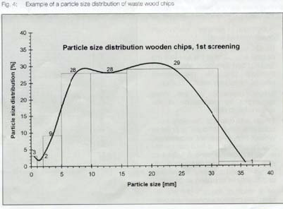
Particle size distribution: |
0 - 70 mm, (Figs. 3 & 4) |
Mean particle size: |
approx. 10 mm |
Bulk density: |
approx. 200 kg/m3 |
Solid matter density: |
approx. 800 - 900 kg/m3 |
Temperature: |
approx. 20°C |
Humidity: |
up to 25%, peaks higher |
The particle size distributions is shown by way of example in Fig. 4. As a result of the predominantly heterogeneous material composition, maximal lengths of up to 100 mm are by no means rare.
For this reason alone the transport lines cannot be too small, so that plugging can to all intents and purposes be reliably excluded. This means a high air volume, but since the transport air also participates in combustion the transport balance can, in spite of the large quantites of air necessary and the small burden, be regarded overall as favourable in energetic terms.
When designing the plant special emphasis was laid on simple process engineering and robust design of the units and plant components. As a matter of course the requirements of modern safety technology (such as explosion protection) were also taken into account. The entire plant can also be executed as an open-air design if desired.
The gravity counterflow classifier was designed for the severe operating conditions and optimized empirically. The operator can adapt the classifier speed, and therefore the separating efficiency, to a wide variety in the composition of the waste woods by a manual flap. The only point which requires monitoring is the level of material in the catchpot below the classifier.
The cyclone was designed for minimum pressure drop, velocities and wear while simultaneously providing maximum capture efficiencies. Even fine-grained sand, which is inevitable with wood and bark waste due to the use of bulldozers and other heavy plant equipment, is reliably removed. Although no appreciable wear has up to now been discovered in the cyclone, the wearing zones are replaceable.
Below the cyclone, a flow smoothing chamber is installed and in this way a pressure seal achieved via the knife edge lock in the direction of material extraction. Together with the material in the smoothing chamber the knife edge lock reliably prevents any backflow of air, which even in small quantities would cause a considerable degradation of the capture efficiency. Blocking of the knife edge lock is reliably avoided by the arrangement of the rotary vane dividers and the cutting edges on the casing. Should however the lock exceptionally become jammed due to oversize or foreign bodies, these can be removed via a reversing control after the alarm has been given and transport then recommenced when the obstacle has been removed.
The feeding tee is formed in such a way that on the one hand, a troublefree material admission into the transport line can be maintained, which is assisted by the air injection nozzle, and on the other a technically favourable air flow with a relatively low pressure drop is attained.
3. Advantages of the selected plant configuration
What are then the special advantages of the plant described here? They can be briefly summarized as follows:
- Substitution of expensive fuel through cheap residual wood.
- By distributed pneumatic injection an optimal admission of the fuel into the fluidised bed furnace is ensured and therefore favourable preconditions created for subsequent combustion.
- Simple regulation of the mass throughput by modification of the screw rotation speed.
- Simple and low-cost "co-combustion of wood residues" is possible without high investment expenditure, and the previous fuel feed can be operated in parallel or alone. A "container store" as a temporary fuel reserve can be set up and operated at low cost and its volume increased as desired.
- As a result of the arrangement selected the process engineering is overall simple, especially for the classifier (separation of metals and oversized material)
- Reliable transport of the wood residues with low wear by bypass operation of the fan.
- Problem-free pneumatic transportation without plugging through generously-sized transport lines.
Since the re-equipment of existing combustion plants for co-combustion is possible without high investment costs, the technology described represents an interesting extension of the combustion possibilities for a plant.
4. Operational experience with the experimental plant
As has already been said, the new system was constructed on the basis of experience with the experimental plant. The following statements could be verified as results of the trials lasting for over a year.
The plant has been very largely troublefree in operation on account of the simple and reliable technology. An important step towards troublefree operation was the relocation of the fan into the bypass. Before this decisive improvement, the material to be transported was sucked directly over the fan. In spite of armouring, wear restricted the life of the fan impeller to as little as 2 weeks or less. Fig. 5 shows such an impeller after one week of operation.
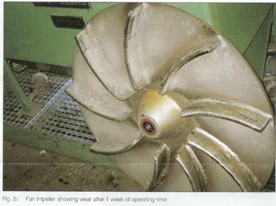
The wear grooves and wastage already mentioned can be very clearly seen. It should be mentioned that it is not only the costs of the wear parts themselves but also the reduced availability and the workshop/assembly costs which represent a severe disadvantage.
Some changes to the sealing system of the knife edge lock were made in order to prevent plugging of the lateral bearing zone with fine wood residues. Additional flushing connections were installed here, for example. In the new plant, a different mechanical solution will be adopted in order to be able to dispense with the complex scouring air connection.
A Gas Solid-Ejector (3) which reliabily avoids air leakage backwards from the conveying line trough knife edge lock to the cyclone, cannot be installed, because of its high energy consumption. Therefore the feeding tee has been re-designed and optimized.
After initial difficulties and an empirical optimization, the pre-separation of the metal parts and oversize in the feeder classifier can be regarded as reliable in operation.
The transport line system could not be optimally routed because of the lack of space in the experimental configuration. Bends with tight circular arcs had to be laid as a result. On the one hand, this produced lower pressure drops in operation, but on the other hand, abrasion wear was concentrated on a smaller surface and therefore the life of the (unlined) elbows was reduced. The same applied to the division of the transport line. For structural reasons it was never possible to achieve an optimal air flow distribution in trial operation. However, the above aspects were taken into account in the redesigned plant.
Right at the experimental stage, the greater distances in the permanent plant were simulated by using additional piping lengths. This was deliberately undertaken in order to avoid later possible surprises should the transport behaviour/pressure drops prove to be different from the experimental set-up.
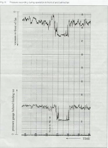
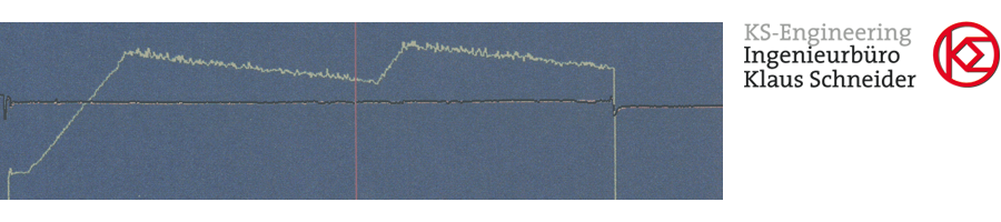
Fig 6 shows a part of a pressure recording during operation at 80% of boiler load. Between 8 p.m. and 9 p.m. the mass flow was reduced and set to about 40% boiler load. The pressure curve is very smooth during the whole operation time.
5. Concluding Remarks
Summarising, it can be said that the experience obtained with the experimental plant has represented or will represent a valuable basis for the new, permanent plant and future projects in this field.
After some modifications to the experimental plant, a high measure of reliability was achieved with a relatively simple and economical technology.
Overall, the retrofitting of the boiler plant for the combustion/co-combustion of wood residues represents a reliable and low-cost technology with considerable commercial and ecological advantages and is therefore of valuable benefit to the overall economy.
References:
- Huschauer, H., Paulsen, W. and Spangenberg, W: Betriebserfahrungen mit der atmosphärischen stationären Wirbelschichtanlage im Kraftwerk Afferde (KW Afferde) der Elektrizitätswerke Wesertal GmbH, Hameln; VDI-Berichte 601, Düsseldorf 1986, pp. 55-68.
- Spangenberg, W.: Neue Betriebsergebnisse mit der Wirbelschichtanlage im KW Afferde; International VGB-Conference „Wirbelschichtfeuerung und Dampferzeugung“, Essen 1988, Vortrag 16.
- Schneider, K.: Use of gas-solid-ejectors as inward transfer units for pneumatic conveying of solids; bulk solids handling Vol. 16 (1996) No. 3, pp. 375-382
![]() PDF-Download
PDF-Download