New Type of Ash-Removal Unit for Smaller Amounts of Ash from Fossilly Fueled Power Stations
Description
The new ash removal unit has developed from a combination of tried and tested modules. The maximum available installation height is very often limited. This is particularly the case in the power station sector. Nevertheless the ash must be drawn off, cooled and transported to the ash-silo some distance away. This is almost always done pneumatically. Any oversize grain can disturb this transportation or even render it impossible.
The newly developed ash removal unit combines the above features with a low installation height, permitting
- the removal of hot ash
- the cooling of the entire volume of discharged ash
- the separation of coarse and fine grain
- the vertical transportation of cooled and separated ash
The energy required by the tried and tested individual modules is low. A test plant to technical scale to determine specific characteristics is available.
Several units can be set up parallel to each other for greater quantities and to maintain the requisite redundancy.
The Design and functioning of the Apparatus
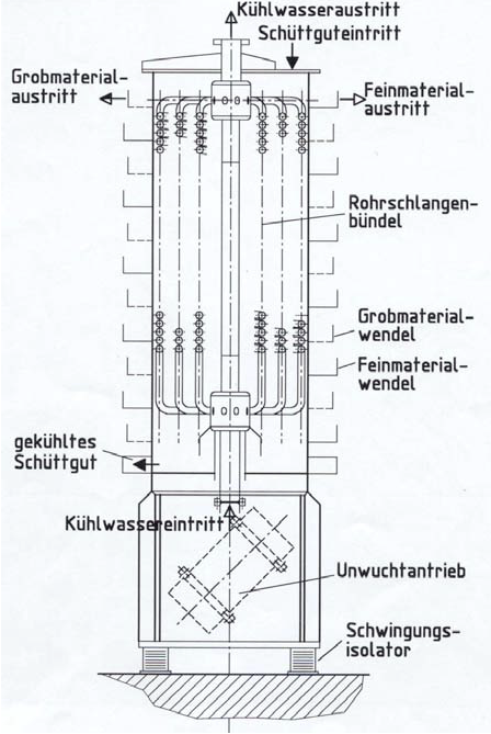
Fig. 1 shows the basic design of the test plant. The hot (or cold) bulk material is fed into the container and sinks down evenly. There is a tube bundle in the inside of the container which absorbs the heat of the bulk material via an external cooling (heating) cycle. Water is usually used as coolant. There are two unbalance motors at the base of the torsionally rigid frame. These motors generate the requisite propulsive power for the bulk material. The cooled material leaves the container via a lateral gap in the floor area and is guided upwards along a screw line with a gradient of approx. 3 - 5° The spiral conveyors may be open or enclosed.
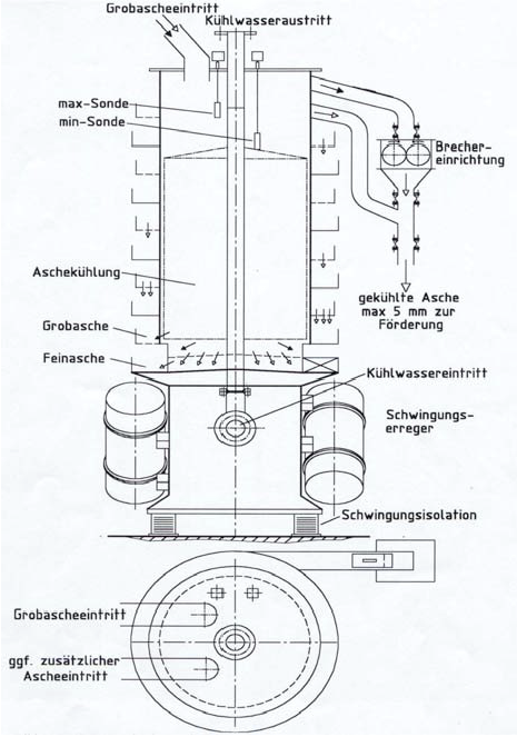
Part of the bottom of the spiral conveyor is designed in the form of a sieve. Length and fineness of the sieve bottom will depend on the desired sieving accuracy and sieving fineness. Oversize grain and sifted material are conveyed upwards separately and can thus be easily separated.The sieving conveyors for dusty or environmentally hazardous bulk material are enclosed so that no dust can penetrate outwards. The cooling water enters at the bottom and leaves at the top, i.e. the plant is operated on the counterfiow principle. The design of the ash-removal unit is adapted to the special requirements. One example is the discharge device for bed ash from circulating fluidized bed furnaces (Figure 2). The plant is also suitable for cooling/heating of refuse incineration slag.
Cooling Capicity
By contrast to the so-called static or stagnation coolers, the movement of the bulk material within the heat exchanger area causes an intensive exchange of particles and at the cooling surface. These continuous particle movements leads to an increase of the convective part in heat transfer. The heat throughput figures for bed ash are approximately 80 W/m² for cooling from 700°C to 100°C, for example. This causes a substantial reduction in the requisite heat exchange surface, leading to a compact, high performance and low-wear unit which, combined with a low susceptibility to faults and low maintenance, constitutes a good alternative to known systems.
Design requirements
The following table summarises the characteristic data from the measurements in the test plant for 4 standard sizes.
Type |
1 |
2 |
3 |
4 |
max. throughput [t/h] |
2,5 |
5 |
10 |
20 |
cooling rate for DJlog=192,5 K [kW] |
298 |
596 |
1191 |
2382 |
cooling water requirement for |
12,8 |
25,6 |
51,3 |
102,6 |
max. input temperature for bulk material [°C] |
700 |
700 |
700 |
700 |
output temperature of bulk |
100 |
100 |
100 |
100 |
electric power consumption [kW] |
2 x 1,5 |
2 x 3,5 |
2 x 6,0 |
2 x 8,0 |
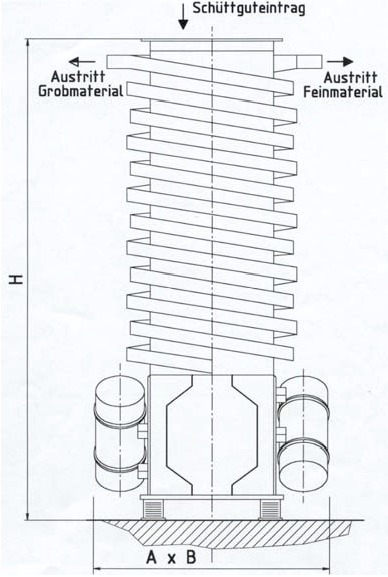
dimensions (see fig. 3) |
|
|
|
|
A x B [mm] |
1300 x 1000 |
1600 x 1400 |
1800 x 1800 |
2200 x 2200 |
H [mm] |
2500 |
3000 |
3500 |
4000 |
Figure 3 shows the main dimensions. The material selection and outfitting of the apparatus is made in accordance with operating temperature. The ash removal unit will be adapted accordingly to the respective application. Results from tests and measurements with ashes and foundry sands are already available here. Alternatively, a fluidized-bed cooler could be used for fine-grained ash or sand. Corresponding selection sheets are similarly enclosed.
![]() PDF-Download
PDF-Download