Injector Vessel Conveyor Systems
for Low-Pulsation Dosing and Conveying
by K. Schneider, Germany
published in powder handling & processing; Volume 5, Number 1, 3 (1993) pp. 21-25
1. Introduction
Dosing of bulk material is in many cases associated with the transport of the material to the point of distribution. The product frequently has to be distributed from one feeding point to several points of use. In such cases combined dosing/conveying processes offer considerable advantages.
One well-known and frequently employed method is the pneumatic transport of bulk materials.
Dosing, i.e. the controlled feeding of material into the conveying line, is in the majority of cases effected mechanically via screw or rotary feeder. A combination of the two processes has proved successful in many fields of application and represents the technical state of the art.
Such systems are, however, not capable of meeting the severe requirements for high-precision dosing and pulsation-free operation.
For example, the fuel supply to bituminous coal lighting-up burners [1, 2] cannot be effected using this standard combination. Tests with rotary feeders have proved completely unsatisfactory: Since the flame monitoring equipment reacts to variations in flame intensity by shutting down the burner, even higher-frequency pulsations, such as are produced by the irregular discharge from rotary feeder chambers cannot be tolerated for reliable plant operation.
For this reason a new dosing system has been developed and constructed. This system is not only suitable for dosing and conveying but is also capable of supplying various consumers or supply points from one feeding point.
In contrast to the above standard combination the new MDS process is purely pneumatic in nature, i.e. there are no mechanical dosing devices or distributors. The basic design of this Multiline Dosing System (MDS) and the experience gained with such a system are described here.
2. Demands on a Pneumatic Dosing System
A pneumatic dosing system must meet further requirements over and above that of ensuring a high degree of constancy in throughput. The following criteria are of particular importance:
1. As little complexity as possible in the process and control equipment;
2. Low operating and energy costs;
3. Reliability and low wear;
4. Continuous supply of several takeover points from one feeding point;
5. Switching in and out of individual takeover points during plant operation.
As regards pneumatic dosing systems the following can be said:
Volume-restricting dosing systems, such as rotary or screw feeders, require the least complexity in process and control system technology. However, the unavoidable fluctuations of material flow do not always permit the use of such units.
The operating and energy costs of a purely pneumatic dosing system are lower than those for mechanical dosing with subsequent pneumatic transport. Since pneumatic dosing systems do not contain any parts rotating in the solids flow, the wear rate is lower and these systems thus offer higher reliability. This applies in particular to dense-phase transport due to the relatively high loading, i.e. solids/gas mass flow ratio.
The pneumatic dosing system allows for continuous supply of several take-over points from one feeding point without a secondary downstream distributor. Provided the resistance in the parallel pipes is identical, identical gas and solids mass flows pass through the individual lines.
The cutting in out of individual lines enlarges the field of application since intermediate transport speeds or part loads can be relatively easy accommodated.
3. Multiline Dosing System (MDS)
An injector vessel System (Fig. 1) has been designed to comply with the above requirements. This system allows for continuous supply of one or more takeover points from one feeding point and is in particular suited to the dosing and conveying of fine-grained and pulverised bulk materials, such as coal, ash or lime-based products.
The system shown in Fig. 1 has been designed to supply PF lighting-up burners with pulverised bituminous coal. The essential technical data of the system are compiled in Table 1. The overall system and the experience gained with the lighting-up equipment have already been described in another publication [1, 2].
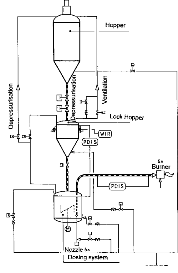
Fig. 1: Process schematic of the dosing system
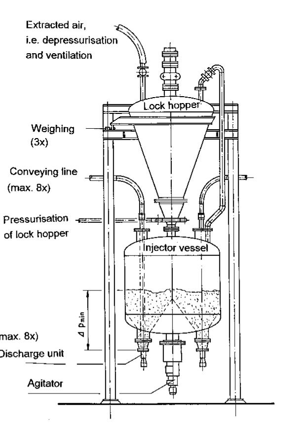
Fig. 2: Basic design of a multiline dosing system
One dosing system is capable of supplying a total of six (max. eight) burners. Fig. 2 shows the design of a multiline dosing system which can be correlated with Fig. 1.
Each conveying line supplies one burner. Since the burners are of identical design and require an identical amount of fuel, the pipe resistances have been carefully adjusted to ensure uniformity. Each conveying line is equipped with a differential pressure gauge which is described in detail below. Each conveying line starts from a so-called discharge unit. These units are uniformly distributed round the bottom of the injector vessel.
The individual lines can be connected or disconnected via pneumatically operated nozzles. A motor-driven agitator material in the injector vessel and the contents are monitored by level gauges. The pressure in the injector vessel is monitored by pressure transducers.
| No. of conveying lines | 1 – 8 |
| Throughput per conveying line | 200 – 3500 kh/h |
| Loading | 10 – 60 kg/kg |
| Conveying line lenght | 10 – 60 m |
| Pressure drop acoss conveying line | 0,5 – 4 bar |
| Possible counter pressure (gauge) | bis 20 bar |
| Gas velocity (outlet) | 8 – 20 m/s |
| Mean particle diameter | 0,04 – 1 mm |
| Bulk desnity | 250 – 1.600 kg/m3 |
Table 1: Range of application for the dosing system MDS
In order to ensure continuous operation of the plant a lock hopper is located above the injector vessel. This discharges material into the transport vessel if the level registered in the vessel drops below a predetermined level. The discharge unit and its control characteristics will now be outlined before describing the exact timing sequence of the conveying system.
3.1 Discharge Unit
The discharge unit is the heart of the dosing system and is installed in the bottom of the injector vessel. Fig. 3 shows the design of a discharge unit which is characterised by two main features:
1. Split-up of the supplied gas flow in two branch flows (discharge gas •VA and transport gas •VF)
2. Nozzle adjustable in height via pneumatic cylinder
The split-up of the total gas flow into transport gas •VF and discharge gas •VA allows for throughput variations. At constant gas flow the amount of solids discharged per unit time increases with an increasing discharge gas fraction. (Since the transport gas must not necessarily be compressed air, it is hereinafter referred to as the gas flow).
The adjustable throughput range depends on the material and is from about 2:1 to 4:1.
Fig. 4 shows the mass flow, the loading and the corresponding pressure in the vessel for pulverised coal as a function of the discharge gas fraction. The adjustable nozzle isolates the conveying line from the vessel. For this purpose the nozzle is lowered into direct contact with the conveying line by means of a pneumatic cylinder. This interrupts the solids flow and the line can be blown through. The distance between the vessel bottom and the start of the conveying line is dimensioned so that large foreign bodies cannot enter the line and lead to clogging. The vessel remains pressurised so that solids transport can be resumed by simply opening the nozzle.
The ability to shut off a given conveying line or lines enables the plant to operate at part-load when required, i.e. individual burners or burner groups can be optionally connected or disconnected. The isolated conveying lines of the burners can be permanently supplied with purging gas •VS (e.g. for cooling purposes) via the closed nozzle.
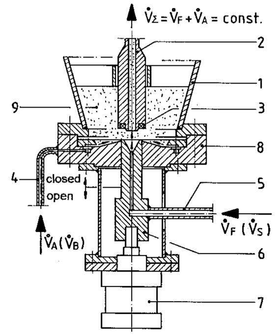
1. = injector vessel;
2. = conveying line;
3. = seal;
4. = discharge gas/pressurizing gas connection;
5. = transport gas/purging connection;
6. = vertically adjustable nozzle (open/closed);
7. = discharge unit bottom with annular gap and guide surface for discharge air;
8. = solids/bulk material
Fig 3: Discharge unit
3.2 Variation and Monitoring of Solids Throughput
With the above discharge unit, the solids flow through the conveying lines can be easily varied and monitored. Mechanically moving parts or a fluidisation of the bulk material with all the inherent disadvantages of such systems are thus not required.
Fig. 3 shows that the incoming gas flow (total gas flow) is split up into two branch flows (transport gas and discharge gas). The transport gas •VF is admitted centrally into the lower end of the conveying line, and transports and aerates the bulk material entering together with the lateral discharge gas flow •VA Fluidisation has been deliberately avoided. Material flow into the conveying line is effected on one hand by gravity and on the other by the impulse of the annular gas flow which has a relatively high velocity.
The total gas flow •VΣ is kept constant in order to realise stable conveying conditions in the solids lines over the full turndown range. This means that there is a constant velocity at the line outlet and varying pressures and velocities at the conveying line inlet. The loading, i.e. solids/gas flow ratio varies (see Fig. 4)
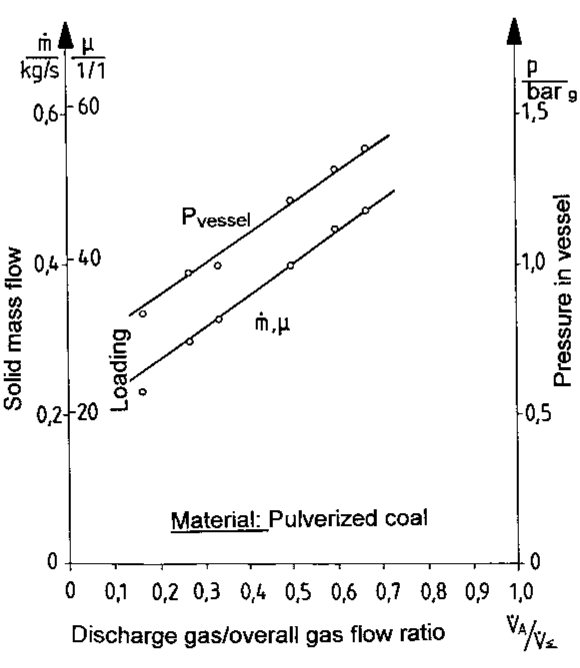
Fig 4: Throughput diagram of a conyeing line
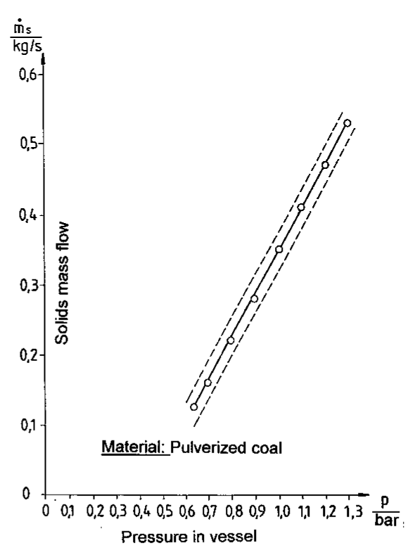
Fig 5: Solids mass flow as a function of pressure in the vessel
It is obvious that there is a practically linear dependence between solids throughput and discharge gas/total gas flow ratio. The same applies to the corresponding pressure in the vessel. In operation the curves shown should be approached as closely as possible. It should be noted that they will vary according to the solid being transported. Calibration curves must therefore be plotted for each type of solid.
The shape of the curve, too, varies in relationship to the bulk material, i.e. some calibration curves are no longer linear but have for example a parabolic form. The limits for the maximum discharge gas fraction also vary from material to material. Granular material with a discharge gas fraction of 95 % can be conveyed whereas the limit for finegrained material is around 80 % or even less. If these values are exceeded, ihe conveying line may become clogged.
Fig. 5 shows the solids mass flow as a function of the pressure in the vessel. Here the corresponding vessel pressure in the vessel has been stabilised during setting of the discharge gas fraction. For this purpose the excess gas is admitted to the injector vessel through the “pressure adjustment“ connection. Discharge of the solids downwards into the conveying lines causes an increase in the gas volume above the bulk material and leads to pressure reduction if not compensated for by admission of excess gas as above. These pressure variations can directly influence the mass flow, but may be evened out by appropriate injection of excess gas above the bulk material.
This ensures that the mass flow through the conveying lines is kept constant and the dosing quality is further improved (see Fig. 5). With a superimposed pressure control system dosing errors caused by the solid material can be reduced to less than 2-5 %.
3.3 Operation Sequence of the Multiline Dosing System
When material is required by one or more consumers the nozzles of the corresponding discharge unit are opened after the respective gas flows have been established.
For this purpose there must be a sufficiently high pressure in the injector vessel. If a specified level (∆Pmin in Fig. 2) is not reached more material must be supplied, i.e. the gravity lock hopper is filled with material from a storage tank (see Fig. 6). Then the lock hopper is pressurised to the same level as that of the injector vessel. Now the overflow line between lock hopper/injector vessel and the material shut-off valve are opened and the material flows into the injector vessel. Following this process the lock hopper is decoupled from the injector vessel and depressurised to ambient pressure.
In particular in the case of fine cohesive dusts the compressed material cannot be discharged from the lock hopper, or only with difficulty. An effective remedy in this event is provided by a special lock hopper pressurisation process. Right at the filling stage care is taken that the bulk material is suitably aerated with gas. This process, developed and tested in a pilot plant, ensures smooth and trouble-free transport.
Weighing the injector vessels allows the overall flow for all lines to be determined. If there are several conveying lines, the individual lines are separately checked via differential pressure gauges.
4. Initial Results with MDS
4.1 Pressure Measurements and Pulsations
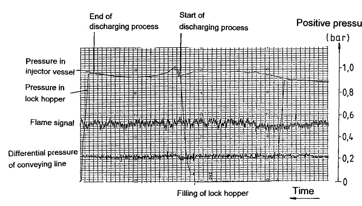
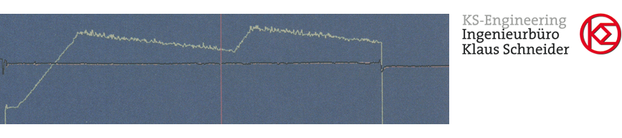
Fig 6: Pressure curve of the MDS
Fig. 6 shows the pressure curve of the dosing system already mentioned. Besides the pressures in the vessels the differential pressure of a conveying line plus the associated flame signal is also plotted. Since pressure stabilisation had not been realised at the time when this record was made, the influence of pressure variations in the vessels on the differential pressure measurement can be clearly seen.
This resulted in mass flow variations of up to 8 %. Pressure stabilisation made it possible to greatly reduce these dosing errors (see Item 3.2). Furthermore, Fig. 6 shows extremely low-pulsation transportation which is totally incapable of producing any response from the flame monitor.
4.2 Throughput and Distribution
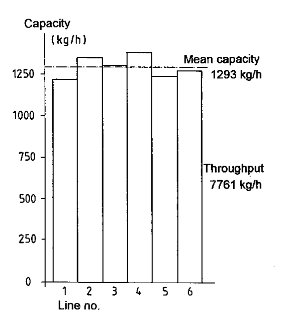
Fig 7: Throughput distributuion of a 6-line dosing system
Fig. 7 shows the capacities of the individual lines (6-line dosing system). Burner stability represented the decisive factor for adjustment of the capacity, so that a given amount of deviations was quite intentional. The minimum height of material in the vessel and the associated pressure difference between the individual discharge units allow, depending on the type of solid, a trimming reserve of up to 15 % in the capacity of the line in question.
4.3 Operational Sequence and Reliability
The individual lines are monitored by differential pressure gauges. Open-loop or closed-loop controls utilising the differential pressure as actual-value signal represents the latest state of the art (3); this has however not been realised in the present case. Monitoring is limited to possible pressure variations in the line which could represent imminent plugging. The system reacts by closing the nozzle and simultaneously increasing the purging gas flow. This invariably disposes of any incipient plugging. Disturbances caused by clogged conveying lines have so far not occurred.
This control sequence also permits further discharge of material from the lock hopper into the injector vessel without difficulty. If a lock hopper charge has not been completely emptied into the injector vessel, the sequence can be repeated and the remaining material is then discharged in the second cycle.
To sum up it can be said that experience with the new dosing system has been very good and operation has so far proved troublefree to a large extent.
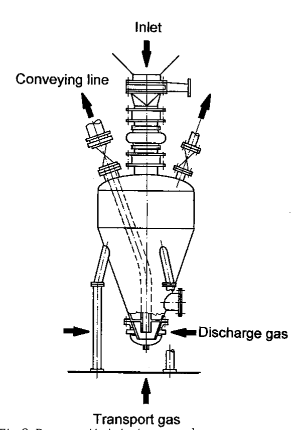
Fig 8: Pneumatic injector vessel
5. Further Fields of Application
5.1 Transport
Series production has already been initiated in order to make use of the advantages offered by the dosing system even for pure transport purposes and to reduce the manufacturing costs. Our own measurements and recent investigations by other authors [4] have shown that pressure vessels with top discharge are capable of carrying higher loads than those with bottom discharge.
These pressure vessels are also equipped with a discharge bottom and the gas flow is split up into transport gas, discharge gas and excess gas. However, the bottom is of simpler design and the conveying line is isolated by a pinch valve or a ball valve outside the vessel. Fig. 8 shows the design of such a vessel.
These units are used for the pneumatic transport of fly ash and bed ash in firing systems and for conveying lime products and inert material (sand). Flow restrictors in the conveying and discharge gas-lines allow the required material throughput to be adjusted during commissioning.
Furthermore, by adjusting the gap width between the start of the conveying line and the vessel bottom it is possible to ensure that only material with a certain grain size can enter the conveying line so that the latter cannot become clogged. The coarse particles are either pulverised and then conveyed or removed by hand.
5.2 Dosing under Extreme Conditions
The dosing system can also be successfully employed in processes where high pressures and temperatures must be overcome. For example, in entrained-flow coal gasification where coke slack is reinjected and distributed against pressures of up to 20 bar and temperatures of up to 300°C, the multiline dosing system is absolutely essential. Experience is already available with these pressure and temperature ranges.
As has been mentioned before the transport gas must not necessarily be air; argon, nitrogen and superheated steam have also been used as carrier media. In these applications the advantage of low-pulsation conveying exerts its full effect, since the processes and reactions are often very sensitive to variations in pressure and/or mass flow.
6. Future Prospects
The MDS pneumatic dosing system meets the requirement for a low-pulsation and highly stable dosing and conveying system. Operational safety and reliability, associated with the advantages offered by multiline dosage, have been demonstrated in practice. Moreover, thanks to its high flexibility the system offers advantages in other fields and can be easily adapted to the prevailing conditions.
References
[1] Rennert, K.D.: Kohlenstaubgefeuerter Zündbrenner (Pulverised-fuel Lighting-up Burners); RWK 34 (1982), pp. 131-135
[2] Rennert, K.D.: Kohlenstaubzündfeuerung: Anwendung, Betriebsergebnisse, Wirtschaftlichkeit (Pulverised-fuel Lighting-up Systems; Application, Operating Results, Efficiency); BWK 36 (1984) pp 217-222
[3] Heep, D.: Dosierung von pneumatisch transportierten Schüttgütern mittels Druckdifferenzsteuerung (Dosing of pneumatically transported bulk material by means of differential pressure control); ZKG 23 (1980), pp.373-374.
[4] Jones, M.G, Mills, 0., Mason, J.S.: A Comparison of the Performance of Top and Bottom Discharge Blow Tank Systems; bulk solids handling 7 (1987) No. 5, pp.701 - 706.
[5] Schneider, K. et al.: Apparatus and Process for Pneumatically Conveying Material in Dust or Finely Particulate Material
![]() PDF-Download
PDF-Download